Variable frequency drive PWM waveform measurements
Warning
The measurements dealt with in this clause involve potentially lethal voltage and current levels. Only qualified individuals, familiar with the construction and operation of the equipment and hazards involved should take these measurements.
Instrumentation
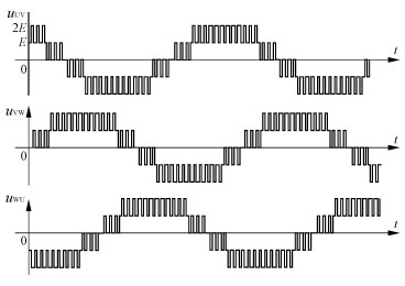
Variable frequency drives (VFD) supply ac induction motors with Pulse Width Modulation (PWM) voltage, which is non-sinusoidal, we called it PWM VFD. Measurements of the PWM voltages must be taken with proper equipments in order to be reliable. Modern digital measurement instruments that are able to read true rms values must be used. Some of them will not read the fundamental component of a PWM waveform though. Harmonic measurement instruments with fast enough sampling rate are capable of reading both rms and fundamental values of voltage, current and power. An oscilloscope with isolated probes and proper bandwidth is appropriate in most cases.
Parameter measurements
According to the NEMA Application Guide for AC variable frequency drive systems, the recommended instrumentation for the measurement of various parameters should be as described in the table below.
Grounding considerations
Safe, reliable and interference-free measurements depend on good grounding practices. The manufacturer's recommendations as well as local regulations concerning grounding must always be followed when installing ground wiring.
Grounding of control
The control must be solidly grounded to the main distribution system ground. A ground common with electrical welding equipment or large current electrical equipment (typically 5x rating of the control) should not be used. If either of these these conditions exist an isolation transformer sized for the installed control with a wye secondary neutral solidly grounded should be used. Where more than one control is used, each of them should be grounded directly to the system ground terminal - they should not be loop grounded nor installed in series.
Grounding of motor
The output ground conductor may be run in the same conduit as the AC motor power leads. The grounded metal conduit carrying the output power conductors can provide EMI shielding, but it does not provide an adequate ground for the motor; a separate ground conductor should be used. The motor's ground wire should not be connected to the metallic conduit.
Measurement procedures
Actual operation conditions (especially concerning motor speed, control type and switching frequency) should be attended when measuring the variable frequency drive PWM wave form. It is worth noting that higher speeds imply higher voltage levels and therefore operation at the highest speed within the operation frequency range will probably result in the highest possible voltage peaks at the motor terminals.
Waveform visualization
The correct evaluation of a variable frequency drive system strongly depends on a proper analysis of the waveforms measured. The visualization of one cycle (or specific parts of a cycle) of the PWM voltage waveform at the motor terminals gives an idea about the pulses' quality at the motor terminals. For a better verification of the consistency of these pulses, the visualization of two or three cycles is recommended, once it evidences the repetitiveness of such pulses. A detailed analysis of a single pulse finally allows that conclusions about the rise time and the intensity of the peak voltages be found.
Oscilloscope scale setting
The better choice of which scale should be adopted while taking variable frequency drive output waveform measurements will evidently depend on the magnitudes of the electrical quantities being measured. However, the ranges shown in the table below are commonly suitable for 50/60 Hz measurements and can be used as a first orientation.
Suggestions of oscilloscope's scale setting
Triggering
Oscilloscopes are instruments ordinarily employed for metering and not for monitoring electrical quantities. In spite of that, the trigger of some modern oscilloscopes can be suitably set, so that it is enabled to hold data of particular interest, for instance waveforms of voltage peaks taken during transient conditions such as acceleration and deceleration periods.
The measurements dealt with in this clause involve potentially lethal voltage and current levels. Only qualified individuals, familiar with the construction and operation of the equipment and hazards involved should take these measurements.

Instrumentation
Variable frequency drives (VFD) supply ac induction motors with Pulse Width Modulation (PWM) voltage, which is non-sinusoidal, we called it PWM VFD. Measurements of the PWM voltages must be taken with proper equipments in order to be reliable. Modern digital measurement instruments that are able to read true rms values must be used. Some of them will not read the fundamental component of a PWM waveform though. Harmonic measurement instruments with fast enough sampling rate are capable of reading both rms and fundamental values of voltage, current and power. An oscilloscope with isolated probes and proper bandwidth is appropriate in most cases.
Parameter measurements
According to the NEMA Application Guide for AC variable frequency drive systems, the recommended instrumentation for the measurement of various parameters should be as described in the table below.
| Parameter | Typical Reading | Instrumentation Required | Reason |
| Control input voltage | Fundamental | Analog or digital voltmeter | Very control input voltage |
| Transient | 20 MHz or higher storage oscilloscope | Capture line voltage variation | |
| Control output voltage or motor input voltage | Fundamental | A meter capable of measuring fundamental of a non-sinusoidal wave form | Very motor input voltage |
| Peak transient and dV/dt | Oscilloscope with a sampling rate of at least 1Ms/sec | Compare to the motor's peak voltage and rise-time with sand capability | |
| Control input current | True ms | True ms meter | Very feeder size |
| Control output current or motor input voltage | True ms | True ms meter | Estimate overheating |
| Fundamental | A meter capable of measuring fundamental of a non-sinusoidal wave form | Estimate torque | |
| Input voltage harmonics | Fundamental plus harmonics | Spectrum analyzer | Ensure compliance with IEEE-519 |
| Input current harmonics | Fundamental plus harmonics | Spectrum analyzer | Ensure compliance with IEEE-519 |
| VFD efficiency | NA | NA |
Not practical due to difficulty of accurately measuring motor output in sinusoidal |
Grounding considerations
Safe, reliable and interference-free measurements depend on good grounding practices. The manufacturer's recommendations as well as local regulations concerning grounding must always be followed when installing ground wiring.
Grounding of control
The control must be solidly grounded to the main distribution system ground. A ground common with electrical welding equipment or large current electrical equipment (typically 5x rating of the control) should not be used. If either of these these conditions exist an isolation transformer sized for the installed control with a wye secondary neutral solidly grounded should be used. Where more than one control is used, each of them should be grounded directly to the system ground terminal - they should not be loop grounded nor installed in series.
Grounding of motor
The output ground conductor may be run in the same conduit as the AC motor power leads. The grounded metal conduit carrying the output power conductors can provide EMI shielding, but it does not provide an adequate ground for the motor; a separate ground conductor should be used. The motor's ground wire should not be connected to the metallic conduit.
Measurement procedures
Actual operation conditions (especially concerning motor speed, control type and switching frequency) should be attended when measuring the variable frequency drive PWM wave form. It is worth noting that higher speeds imply higher voltage levels and therefore operation at the highest speed within the operation frequency range will probably result in the highest possible voltage peaks at the motor terminals.
Waveform visualization
The correct evaluation of a variable frequency drive system strongly depends on a proper analysis of the waveforms measured. The visualization of one cycle (or specific parts of a cycle) of the PWM voltage waveform at the motor terminals gives an idea about the pulses' quality at the motor terminals. For a better verification of the consistency of these pulses, the visualization of two or three cycles is recommended, once it evidences the repetitiveness of such pulses. A detailed analysis of a single pulse finally allows that conclusions about the rise time and the intensity of the peak voltages be found.
Oscilloscope scale setting
The better choice of which scale should be adopted while taking variable frequency drive output waveform measurements will evidently depend on the magnitudes of the electrical quantities being measured. However, the ranges shown in the table below are commonly suitable for 50/60 Hz measurements and can be used as a first orientation.
Suggestions of oscilloscope's scale setting
| Visualization | X-axis | Y-axis |
| 1 cycle | 1 - 2 ms / div | 100 - 500 V / div |
| 3 cycles | 5 - 10 ms / div | 100 - 500 V / div |
| 1 pulse | 0.1 - 10 μs / div | 100 - 500 V / div |
Triggering
Oscilloscopes are instruments ordinarily employed for metering and not for monitoring electrical quantities. In spite of that, the trigger of some modern oscilloscopes can be suitably set, so that it is enabled to hold data of particular interest, for instance waveforms of voltage peaks taken during transient conditions such as acceleration and deceleration periods.
Post a Comment:
You may also like:
Featured Articles
Variable Frequency Drive Sizing
 Before selecting the size of a variable frequency drive (VFD), it is necessary to generally know the working environment, the ...
 Before selecting the size of a variable frequency drive (VFD), it is necessary to generally know the working environment, the ...
Variable Frequency Drive Basic Safety ...
 This paper provides guidelines on functional safety considerations when selecting and integrating a variable frequency drive ...
 This paper provides guidelines on functional safety considerations when selecting and integrating a variable frequency drive ...
Variable Frequency Drives control AC motor for energy savings by adjustable speed, for short VFD, also named variable speed drives and frequency inverter.
