Home » Theory
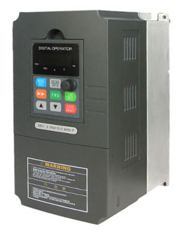 Thirty years ago when we were first seeing 30 hp variable frequency drive (VFD) the size of a refrigerator (and now the size of a brief case), and there was no such thing as a severe duty motor, and it was an absolute TABOO to use a variable frequency drive (VFD) for variable speed. Actually for variable-torque applications, severe duty motors are not required... You are just wasting money for the severe duty motor!
When using single stage pumps, the pump speed is critical, and the pump curve should be verified. But when using submersible pumps, these are typically multi-stage (maybe 15+ stages) and can be reduced much lower in speed. With centrifugal pumps, of course efficiency drops off. Fans have a much lower threshold as where they become ineffective. We have done many pump and fan variable drive applications in the last 30 years, and turning the speed down has never been a problem... With constant-torque applications, it is not recommended to go below 30% even when using a severe duty motor.
I have used surge testing since 1989 in motor manufacturing, motor repair shops and for field testing of motors. I am a big fan of surge testing and have performed over voltage surge tests on 10,000s of motors. It is the only test which can detect weakened insulation between phases or coils in a connected winding. It is a standard test performed by every reputable motor manufacturer and motor repair shop in the world. And it is an excellent test for verifying insulation in the field.
Surge testing, like hipot testing, can be performed at voltages greater than motor nameplate voltage. It is common to perform hipot and surge testing at voltages well above nameplate voltage to verify that an insulation system can withstand the voltage transients and other mechanical stresses which occur at start up. The recommended field hipot and surge test voltages are 40% or more lower than voltages used by manufacturers and rewinders.
Surge testing, like hipot testing, can be performed at voltages greater than motor nameplate voltage. It is common to perform hipot and surge testing at voltages well above nameplate voltage to verify that an insulation system can withstand the voltage transients and other mechanical stresses which occur at start up. The recommended field hipot and surge test voltages are 40% or more lower than voltages used by manufacturers and rewinders.
Most variable frequency drives (VFD) employ the PWM control method. Variable frequency drives generate the AC by switching the main circuit elements. This principle of operation can be referred to as the noise source.
Noises generated from a variable frequency drive are broadly classified into the following types: those radiated from the cables connected to the VFD and VFD main circuits (I/O), those electromagnetically and electrostatically induced from the signal cables of the peripheral devices close to the main circuit power supply, and those transmitted through the power supply cables.
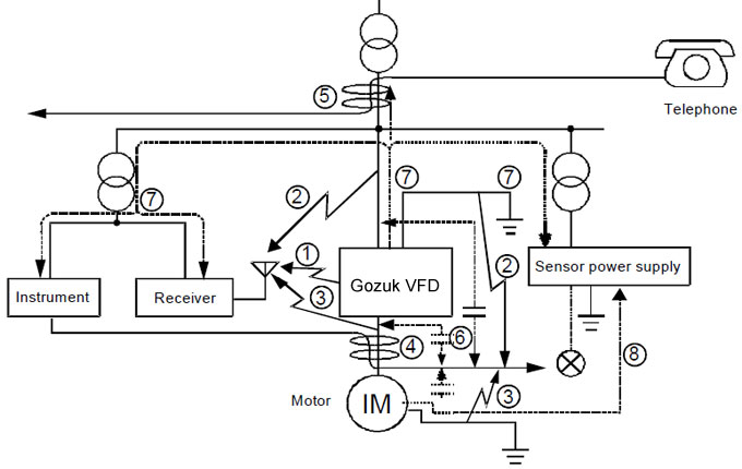
Noises generated from a variable frequency drive are broadly classified into the following types: those radiated from the cables connected to the VFD and VFD main circuits (I/O), those electromagnetically and electrostatically induced from the signal cables of the peripheral devices close to the main circuit power supply, and those transmitted through the power supply cables.

Modern Variable Frequency Drives (VFD) are also provided with tools to get those problems around, so that for instance specific frequencies within the operating range can be skipped and the acceleration/deceleration times can be conveniently adjusted.
Tests realized with several motors and variable frequency drives following the procedures recommended by IEC 60034-14 confirmed that the vibration levels of induction motors increase when these are fed by VFDs.
Furthermore, the observed increment on vibration speeds generally were lower with higher switching frequencies, that is, switching frequency increases tend to reduce the mechanical vibration of the variable frequency drive fed motor.
Today's active filters are constantly monitoring the equipment and only inject enough corrective current to cancel out the harmonic current in the system. So there is no opportunity to ever see a leading power factor. With passive filters, there is a contactor that is controlled by the variable frequency drive to turn on and off the filter to prevent a leading power factor condition. You have 2 devices but as far as function goes, a variable frequency drive preforms work and a filter preforms harmonic mitigation. As far as who to blame is simple. No work bad VFD. No filtering bad Harmonic device. Remember, you can run a VFD without a filter, you can't work without a variable frequency drive. The bottom line is supply the best solution at the most economical price without sacrificing performance.
The characteristics of the cable connecting motor and VFD, as well as its interconnection and physical location, are extremely important to avoid electromagnetic interference in other devices.
Unshielded cables
Unshielded cables
- Three-core unshielded motor cables can be used when there is no need to fulfill the requirements of the European EMC Directives (89/336/EEC).
- Certain minimum distances between motor cables and other electrical cables must be observed in the final installation. These are defined in the table below.
- Emission from cables can be reduced if they are installed together on a metallic cable bridge which is bonded to the earthing system at least at both ends of the cable run. The magnetic fields from these cables may induce currents in nearby metalwork leading to heating and increasing losses.
- They help to reduce the radiated emission through the motor cables in the Radio Frequency range (RF).
- They are necessary when the installation must comply with the EMC Directive 89/336/EEC as per EN 61800-3.
- They are also necessary when using Radio Frequency Interference Filter (whether built-in or external) at variable frequency drive input.
- Minimum distances between motor cables and other electrical cables (for instance, signal cables, sensor cables, etc.) must be observed in the final installation, as per table below.
The lack of international standards that specify test procedures to evaluate the variable frequency drive (VFD) + motor system efficiency allows such tests to be carried out in many different and non contestable ways. Therefore, the results obtained should not influence the acceptance (or not) of the motor, except under mutual accordance between customer and manufacturer. Experience shows the effectiveness of the considerations below.
The effects of speed variation on the motor efficiency can be understood from the analysis of the behavior of the variable frequency drive fed motor output power as a function of its operation speed.
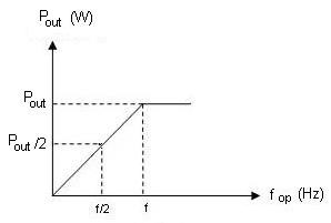
The effects of speed variation on the motor efficiency can be understood from the analysis of the behavior of the variable frequency drive fed motor output power as a function of its operation speed.

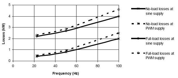
The induction motor, when under Pulse Width Modulation (PWM) voltage coming from the variable frequency drive (VFD), is subjected to voltage harmonics (frequency components above the fundamental frequency). Depending on the type of PWM employed, the switching frequency and other peculiarities of the control, the motor may present efficiency decrease and losses, temperature, noise and vibration levels increase.

Pulse Width Modulation (PWM) voltage source variable frequency drives (VFD) presently comprehend the most used equipments to feed low voltage industrial motors in applications that involve speed variation. PWM VFD works as an interface between the energy source (AC power line) and the induction motor.
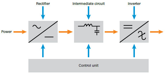
The following diagram depicts the three stages of a Pulse Width Modulation VFD.

The VFD vector control considers the instantaneous electrical quantities referred to the rotor linkage flux as vectors and its equations are based on the spatial dynamic model of the motor.
The following diagram depicts the three stages of a Pulse Width Modulation VFD.

The VFD vector control considers the instantaneous electrical quantities referred to the rotor linkage flux as vectors and its equations are based on the spatial dynamic model of the motor.
The VFD that I selected and ordered for the control of a standard 1,1kW induction motor in the electric laboratory is from the manufacturer Gozuk. Out of a whole list of VFDs this one seemed the best for future experiments in a practical course about control of electric motors and the simulation of an electric vehicle. The vector control VFD, Gozuk made, is a standard but modern VFD with a lot of opportunities to explore, like open loop and closed loop vector control. The variable frequency drive is developed to control induction motors in an automated environment. This includes that many of the possibilities of the vector variable frequency drive cannot be discovered without additional automation tools to deliver feedback to the vector variable frequency drive. In this paper the connection is made with the theory about VFD.
This guideline discusses variable frequency drive (VFD) basic working principle and how installing variable frequency drives in appropriate applications could save energy, cut costs and increase profit margins.
Whilst there are a number of variations in variable frequency drive design; they all offer the same basic functionality which is to convert the incoming electrical supply of fixed frequency and voltage into a variable frequency and variable voltage that is output to the motor with a corresponding change in the motor speed and torque. The motor speed can be varied from zero rpm through to typically 100-120% of its full rated speed whilst up to 150% rated torque can be achieved at reduced speed. The motor may be operated in either direction.
Variable frequency drives applied to AC motors are by far the most common. Variable frequency drives are typically 92-98% efficient with 2-8% losses being due to additional heat dissipation caused by the high-frequency electrical switching and the additional power required by the electronic components.
Whilst there are a number of variations in variable frequency drive design; they all offer the same basic functionality which is to convert the incoming electrical supply of fixed frequency and voltage into a variable frequency and variable voltage that is output to the motor with a corresponding change in the motor speed and torque. The motor speed can be varied from zero rpm through to typically 100-120% of its full rated speed whilst up to 150% rated torque can be achieved at reduced speed. The motor may be operated in either direction.

Variable frequency drives applied to AC motors are by far the most common. Variable frequency drives are typically 92-98% efficient with 2-8% losses being due to additional heat dissipation caused by the high-frequency electrical switching and the additional power required by the electronic components.
Featured Articles
PWM Variable Frequency Drive ...
 Pulse Width Modulation (PWM) voltage source variable frequency drives (VFD) presently comprehend the most used equipments to feed ...
 Pulse Width Modulation (PWM) voltage source variable frequency drives (VFD) presently comprehend the most used equipments to feed ...
Variable Frequency Drive Working ...
 This guideline discusses variable frequency drive (VFD) basic working principle and how installing variable frequency drives in ...
 This guideline discusses variable frequency drive (VFD) basic working principle and how installing variable frequency drives in ...
Variable Frequency Drives control AC motor for energy savings by adjustable speed, for short VFD, also named variable speed drives and frequency inverter.
