VFD Harmonics increase motor losses
The induction motor, when under Pulse Width Modulation (PWM) voltage coming from the variable frequency drive (VFD), is subjected to voltage harmonics (frequency components above the fundamental frequency). Depending on the type of PWM employed, the switching frequency and other peculiarities of the control, the motor may present efficiency decrease and losses, temperature, noise and vibration levels increase.
Furthermore other effects may appear when induction motors are fed by variable frequency drives. Insulation system dielectric stress and shaft voltages allied with potentially damaging bearing currents are well known side effects. Although not produced specifically by harmonics but by other matters that will soon be approached, these are important effects and should not be neglected. The motor current and voltage waveforms when under PWM supply are illustrated below.
Then the motor fed by VFD sees a pulsating (PWM) voltage and a practically sinusoidal current, so that the voltage harmonics generally present higher magnitudes than the current harmonics.
There are basically the following solutions to mitigate the harmonics generated by a PWM VFD:
* All VFDs manufactured by Gozuk employ Space Vector Modulation.
Normative considerations about the variable frequency drive output harmonics
There is no international standardization defining maximum acceptable values for voltage and current harmonic distortion. However, the international standards do consider the increase of motor losses due to the non-sinusoidal supply.
IEC 60034-17 provides an example of motor losses increase owing to PWM supply. Motor info: 315 IEC frame, rated torque and speed values.
Losses caused by fundamental frequency
A – Stator winding losses
B – Rotor winding losses
C – Iron losses
D – Additional load losses
E – Frictional losses
Losses caused by harmonics
F – Stator winding losses
G – Rotor winding losses
H – Iron losses
I – Additional load losses
J – Commutation losses
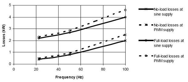
IEC 60034-25 illustrates the motor losses increase due to PWM supply by means of the following curves:

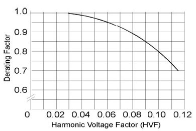
NEMA MG1 – Part 30 considers a derating factor (torque reduction) to avoid excessive overheating of a general purpose motor fed by variable frequency drive, compensating for the circulation of harmonic currents due to the PWM voltage harmonic content:

n: order of the odd harmonic, not including those divisible by three
Vn: per unit magnitude of the voltage at the nth harmonic frequency
Furthermore other effects may appear when induction motors are fed by variable frequency drives. Insulation system dielectric stress and shaft voltages allied with potentially damaging bearing currents are well known side effects. Although not produced specifically by harmonics but by other matters that will soon be approached, these are important effects and should not be neglected. The motor current and voltage waveforms when under PWM supply are illustrated below.
|
PWM voltage at the VFD output |
VFD fed motor current |
 |
 |
Then the motor fed by VFD sees a pulsating (PWM) voltage and a practically sinusoidal current, so that the voltage harmonics generally present higher magnitudes than the current harmonics.
There are basically the following solutions to mitigate the harmonics generated by a PWM VFD:
|
Methods of reduction of harmonics |
Solution characteristics |
|
Installation of output passive filters (L, LC (sinusoidal), dV/dt) |
Installation costs increase |
|
Restrictions for vector control operation |
|
|
Voltage drop (motor horsepower reduction) |
|
|
Use of multi-level variable frequency drives |
Costs increase |
|
Variable frequency drive reliability decrease |
|
|
Control complexity increase |
|
|
Pulse Width Modulation quality improvement (optimization of pulse patterns) |
Space Vector Modulation (SVM)* |
|
Do not increase costs |
|
|
Voltage control upgrade |
|
|
Higher system (variable frequency drive + motor) efficiency |
|
|
Switching frequency increase |
Variable frequency drive efficiency decrease (higher switching losses) |
|
Common mode leakage current flow increase |
Normative considerations about the variable frequency drive output harmonics
There is no international standardization defining maximum acceptable values for voltage and current harmonic distortion. However, the international standards do consider the increase of motor losses due to the non-sinusoidal supply.
IEC 60034-17 provides an example of motor losses increase owing to PWM supply. Motor info: 315 IEC frame, rated torque and speed values.
Losses caused by fundamental frequency
A – Stator winding losses
B – Rotor winding losses
C – Iron losses
D – Additional load losses
E – Frictional losses
Losses caused by harmonics
F – Stator winding losses
G – Rotor winding losses
H – Iron losses
I – Additional load losses
J – Commutation losses
IEC 60034-25 illustrates the motor losses increase due to PWM supply by means of the following curves:

NEMA MG1 – Part 30 considers a derating factor (torque reduction) to avoid excessive overheating of a general purpose motor fed by variable frequency drive, compensating for the circulation of harmonic currents due to the PWM voltage harmonic content:

HVF = √(∑∞n=5 (Vn/n)2)Where
n: order of the odd harmonic, not including those divisible by three
Vn: per unit magnitude of the voltage at the nth harmonic frequency
Post a Comment:
You may also like:
Featured Articles
PWM Variable Frequency Drive ...
 Pulse Width Modulation (PWM) voltage source variable frequency drives (VFD) presently comprehend the most used equipments to feed ...
 Pulse Width Modulation (PWM) voltage source variable frequency drives (VFD) presently comprehend the most used equipments to feed ...
Variable Frequency Drive Working ...
 This guideline discusses variable frequency drive (VFD) basic working principle and how installing variable frequency drives in ...
 This guideline discusses variable frequency drive (VFD) basic working principle and how installing variable frequency drives in ...
Variable Frequency Drives control AC motor for energy savings by adjustable speed, for short VFD, also named variable speed drives and frequency inverter.
