Home » Applications » Select a right Variable Frequency Drive
Select a right Variable Frequency Drive
Before selecting a Variable Frequency Drive (VFD) for an existing electric motor, it's important to know the purpose and characteristics of the different components involved in the process. This paper gives a list of the parameters that I looked at to make my selection about the needed VFD.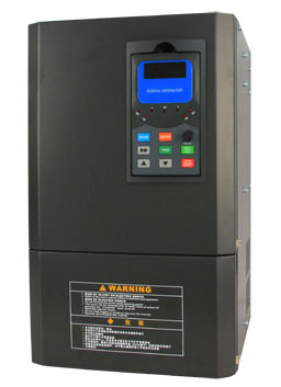
The motor
a. Requirements of installation
Motor Nameplate:
So, knowing that the startup current can be up to 9 times the nominal current, we take 10 times the nominal current as maximum current that the variable frequency drive must able to deliver (50 amps). The nominal power is 1,5kW (1,1kW /efficiency of 0,75). The nominal voltage is at least 220V with three phases. With a higher voltage the motor can keep the same U/f until a higher frequency and voltage. The limitation is the heating of the wires and the resistance against high voltage of the insulation. Because the ventilator is coupled with the motor, the heating isn't a problem for a small over-voltage. The maximal frequency that can be applied to the motor depends on the mechanical characteristics of the motor, for instance the bearings of the motor. Because of harmonics, the maximal power is reduced (10-20%). We take 10% because the non-continue cycle of the motor. This gives an active power of 1,7 - 1,875 kW. For the simulation of an electric vehicle drive with battery pack, choose a VSI variable frequency drive with variable DC-voltage is needed or a common VSI and a variable frequency drive on the batteries to maintain a constant voltage.
b. Speed regulation range, cooling
The range of the speed depends on the mechanical characteristics of the motor and the load power. It's interesting to get the speed over 2 *n0 because then the three different regions can be seen (constant torque, constant power and parabolic decreasing power region). Here for the frequency has to be higher than 150 Hz (Often the limitations are 400 Hz based on mechanics)
c. Power consumption of control and motor
If possible the VFD can improve the power factor of the motor for instance with voltage vector control. The efficiency of most VFDs is higher than 95% so the additional power load isn't significant.
d. Working quadrants
It's useful to choose a 4 quadrant variable frequency drive. This way DC-braking, AC-braking with resistor and/or maybe AC-braking with recovery can be done. Regenerative braking is also used in an electric vehicle so if an inert load is used this can be implemented in an experiment. The possibility of regenerative braking is not a major point to make the selection, more an interesting bonus.
e. Torque course, run-up torque, acceleration torque
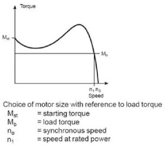
The starting torque is 2.5*nominal torque, the breakdown torque is 3*nominal torque. The acceleration torque depends on the load. Most of the loads have a linear or square course. Another possibility is the unloaded acceleration where the actual load is put in when the motor is at its highest speed, this limits the start current.
f. Slip compensation
Slip compensation is useful to have an automatic control of a constant speed. Here the frequency change can be measured. This is an interesting experiment although we have to be cautious for the different automatic settle processes present in the variable frequency drive control.
g. Needed run-up and run-off characteristics
It's of course very interesting to have a large scale of pre-programmed run-up and run-off cycles and/or the possibility to program such cycles.
If possible, the application of AC and DC braking is interesting and can help to do more measurements. Of course we have to adjust the brake times to limit the heat dissipation and overvoltage in the interstage. When such overvoltage is reached, the variable frequency drive should be decoupled so the motor runs off free.
i. Mass moment of inertia
De mass moment of inertia depends on the load. If we want to simulate an electric vehicle, the mass moment of inertia is rather high what includes slow acceleration and deceleration and high transition currents. Also the first law of thermodynamics is valid: the kinetic energy of the load and motor has to be equal to the energy on the capacitor of the interstage:
There are several modes of driving the motor which leads to an adjustment of the permitted maximum current and power. This has everything to do with the acceleration and deceleration stages in the operation and the equivalent heat dissipation. For every operation cycle next formula gives the permitted load:
Pm: the rated output power of the motor
X: #starts, brakes or reversals
ts: start or brake time
Is/lb: start current/braking current
K: constant term; 1: starting, 3: braking, 4: reversals
k. Safety
Short-circuit, overload and earth fault safety measures should be present in selection of a variable frequency drive. There has to be also an electronic safety switch for the DC voltage interstage. A variable frequency drive with internal voltage circuit is needed when we want to work with batteries connected to the interstage. I think the safety measures for the laboratory are already high but high safety standards for the variable frequency drive are still needed and very useful for protection of machine and persons.
Environment
a. Installation altitude, influence of ambient temperature
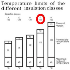
The motor (and by that the variable frequency drive) is installed at an altitude of 1,5m above ground ~ sea level. The ambient temperature is 15-25°C. Like listed at the nameplate, the motor has insulation class F.
b. Need of air cooling, cooling possibilities
There is ventilation of the room and by that of the air around the motor. There is a ventilator mounted at the axle of the motor. Maybe it is needed to reduce maximal allowed current (and torque) of motor at low frequencies. An independent ventilator isn't an option. The cooling of the variable frequency drive may not be a problem in the laboratory. If we chose an IP protection level that isn't very high than the cooling will be no problem. Eventually an additional ventilator can be mounted. The variable frequency drive has a low degree of utility. High IP protection level is not needed because users are well educated and there is no presence of water. Although the interstage has a very high and thus dangerous voltage.
c. Requirements for water, pollution, dust, gasses
There is no need for special requirements in the selection. There is no water source nearby, the working area is a normal electric laboratory (no pollution or gasses) and the room is frequently cleaned. (No significant dust level)
d. Noise
Working in an electric laboratory so there is no special need for reduction of the noise level.
Supply mains
a. Mains voltage
120/220V or 220/380V
b. Mains capacity
13 kW
c. Mains frequency variation
Connected with grid
d. Mains losses
Connected to grid and emergency stop so frequent losses
Maintenance, users
a. Education degree
The users of the motor-VFD combination are on the field of electric machines. There is always supervision by a related technical person.
b. Maintenance need
The motors aren't frequently used so maintenance degree is very low. If maintenance is needed, this will be done by a well educated technical personnel.
c. Spare parts
There is no need to select spare parts unless the VFD broken.
Economic
a. Purchasing cost
Has to be less than 2000 $ for a 1,5 kW VFD and motor.
b. Needed space, kind of construction
The needed space is limited to approximately (80*80*80) which is more than enough. It has to be moveable (chariot or portable) eventually construction on a wooden plate with additional devices has to be possible.
c. Installation cost
The VFD-motor installation will be done by technical person so there will be no significant additional cost.
d. Use of system
The system is selected for end user. It will be frequently used by end user with a low level of knowledge of the system. The characteristics have to be easy adjustable, manual or PC-interface and user friendly.
e. Efficiency whole system
The whole drives system has to be as efficient as possible but this is not a major point of consideration.
f. Need of reactive power
The motor has a cosφ of 0.73
Safety measures (All those measures can be included in the variable frequency drive but can also be placed outside)
a. Galvanic separation
Preferable
b. Electronic temperature guard (PTC-resistor)
Preferable
c. Limitation for over- and under-voltage, voltage increase degree
Preferable
Normalization
a. IEC, CE ( international)
b. SIS (national)

The motor
a. Requirements of installation
Motor Nameplate:
|
AC ~3F 50/60Hz |
IEC34 IP55 |
|
MT90524-4 |
temp.cl. F (new name AA092001ASA) |
|
Pm: 1,1/1,3 kW |
RPM: 1410/1700 |
|
U: 380-420/440-480 V Y |
I: 2,9/2,8 A |
|
U: 220-240/2S0-280 V △ |
I: 5/4,8 A |
|
No. MK110020-5 |
COSφ: 0,73/0,79 |
So, knowing that the startup current can be up to 9 times the nominal current, we take 10 times the nominal current as maximum current that the variable frequency drive must able to deliver (50 amps). The nominal power is 1,5kW (1,1kW /efficiency of 0,75). The nominal voltage is at least 220V with three phases. With a higher voltage the motor can keep the same U/f until a higher frequency and voltage. The limitation is the heating of the wires and the resistance against high voltage of the insulation. Because the ventilator is coupled with the motor, the heating isn't a problem for a small over-voltage. The maximal frequency that can be applied to the motor depends on the mechanical characteristics of the motor, for instance the bearings of the motor. Because of harmonics, the maximal power is reduced (10-20%). We take 10% because the non-continue cycle of the motor. This gives an active power of 1,7 - 1,875 kW. For the simulation of an electric vehicle drive with battery pack, choose a VSI variable frequency drive with variable DC-voltage is needed or a common VSI and a variable frequency drive on the batteries to maintain a constant voltage.
b. Speed regulation range, cooling
The range of the speed depends on the mechanical characteristics of the motor and the load power. It's interesting to get the speed over 2 *n0 because then the three different regions can be seen (constant torque, constant power and parabolic decreasing power region). Here for the frequency has to be higher than 150 Hz (Often the limitations are 400 Hz based on mechanics)
c. Power consumption of control and motor
If possible the VFD can improve the power factor of the motor for instance with voltage vector control. The efficiency of most VFDs is higher than 95% so the additional power load isn't significant.
d. Working quadrants
It's useful to choose a 4 quadrant variable frequency drive. This way DC-braking, AC-braking with resistor and/or maybe AC-braking with recovery can be done. Regenerative braking is also used in an electric vehicle so if an inert load is used this can be implemented in an experiment. The possibility of regenerative braking is not a major point to make the selection, more an interesting bonus.
e. Torque course, run-up torque, acceleration torque

The starting torque is 2.5*nominal torque, the breakdown torque is 3*nominal torque. The acceleration torque depends on the load. Most of the loads have a linear or square course. Another possibility is the unloaded acceleration where the actual load is put in when the motor is at its highest speed, this limits the start current.
f. Slip compensation
Slip compensation is useful to have an automatic control of a constant speed. Here the frequency change can be measured. This is an interesting experiment although we have to be cautious for the different automatic settle processes present in the variable frequency drive control.
g. Needed run-up and run-off characteristics
It's of course very interesting to have a large scale of pre-programmed run-up and run-off cycles and/or the possibility to program such cycles.
- constant current
- constant U/f
- parabolic U/f
- low speed resistance compensation (IR-compensation)
- torque strengthening
- programmable course
If possible, the application of AC and DC braking is interesting and can help to do more measurements. Of course we have to adjust the brake times to limit the heat dissipation and overvoltage in the interstage. When such overvoltage is reached, the variable frequency drive should be decoupled so the motor runs off free.
i. Mass moment of inertia
De mass moment of inertia depends on the load. If we want to simulate an electric vehicle, the mass moment of inertia is rather high what includes slow acceleration and deceleration and high transition currents. Also the first law of thermodynamics is valid: the kinetic energy of the load and motor has to be equal to the energy on the capacitor of the interstage:
j. Operation duration
There are several modes of driving the motor which leads to an adjustment of the permitted maximum current and power. This has everything to do with the acceleration and deceleration stages in the operation and the equivalent heat dissipation. For every operation cycle next formula gives the permitted load:
PP: the permitted power load
Pm: the rated output power of the motor
X: #starts, brakes or reversals
ts: start or brake time
Is/lb: start current/braking current
K: constant term; 1: starting, 3: braking, 4: reversals
k. Safety
Short-circuit, overload and earth fault safety measures should be present in selection of a variable frequency drive. There has to be also an electronic safety switch for the DC voltage interstage. A variable frequency drive with internal voltage circuit is needed when we want to work with batteries connected to the interstage. I think the safety measures for the laboratory are already high but high safety standards for the variable frequency drive are still needed and very useful for protection of machine and persons.
Environment
a. Installation altitude, influence of ambient temperature
The motor (and by that the variable frequency drive) is installed at an altitude of 1,5m above ground ~ sea level. The ambient temperature is 15-25°C. Like listed at the nameplate, the motor has insulation class F.

b. Need of air cooling, cooling possibilities
There is ventilation of the room and by that of the air around the motor. There is a ventilator mounted at the axle of the motor. Maybe it is needed to reduce maximal allowed current (and torque) of motor at low frequencies. An independent ventilator isn't an option. The cooling of the variable frequency drive may not be a problem in the laboratory. If we chose an IP protection level that isn't very high than the cooling will be no problem. Eventually an additional ventilator can be mounted. The variable frequency drive has a low degree of utility. High IP protection level is not needed because users are well educated and there is no presence of water. Although the interstage has a very high and thus dangerous voltage.
c. Requirements for water, pollution, dust, gasses
There is no need for special requirements in the selection. There is no water source nearby, the working area is a normal electric laboratory (no pollution or gasses) and the room is frequently cleaned. (No significant dust level)
d. Noise
Working in an electric laboratory so there is no special need for reduction of the noise level.
Supply mains
a. Mains voltage
120/220V or 220/380V
b. Mains capacity
13 kW
c. Mains frequency variation
Connected with grid
d. Mains losses
Connected to grid and emergency stop so frequent losses
Maintenance, users
a. Education degree
The users of the motor-VFD combination are on the field of electric machines. There is always supervision by a related technical person.
b. Maintenance need
The motors aren't frequently used so maintenance degree is very low. If maintenance is needed, this will be done by a well educated technical personnel.
c. Spare parts
There is no need to select spare parts unless the VFD broken.
Economic
a. Purchasing cost
Has to be less than 2000 $ for a 1,5 kW VFD and motor.
b. Needed space, kind of construction
The needed space is limited to approximately (80*80*80) which is more than enough. It has to be moveable (chariot or portable) eventually construction on a wooden plate with additional devices has to be possible.
c. Installation cost
The VFD-motor installation will be done by technical person so there will be no significant additional cost.
d. Use of system
The system is selected for end user. It will be frequently used by end user with a low level of knowledge of the system. The characteristics have to be easy adjustable, manual or PC-interface and user friendly.
e. Efficiency whole system
The whole drives system has to be as efficient as possible but this is not a major point of consideration.
f. Need of reactive power
The motor has a cosφ of 0.73
Safety measures (All those measures can be included in the variable frequency drive but can also be placed outside)
a. Galvanic separation
Preferable
b. Electronic temperature guard (PTC-resistor)
Preferable
c. Limitation for over- and under-voltage, voltage increase degree
Preferable
Normalization
a. IEC, CE ( international)
b. SIS (national)
Post a Comment:
You may also like:
Featured Articles
Variable frequency drive for water ...
 Quantifying the energy efficiency of pump units across markets is a tough task: These units mostly consist of rotodynamic pumps ...
 Quantifying the energy efficiency of pump units across markets is a tough task: These units mostly consist of rotodynamic pumps ...
Single VFD for Multiple Motors
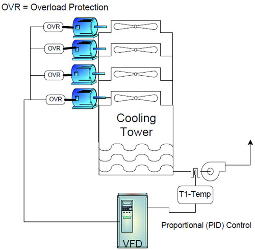 A single variable frequency drive (VFD) may control 2 or 3 motors at a time, multiple motors control is usually done because of ...
 A single variable frequency drive (VFD) may control 2 or 3 motors at a time, multiple motors control is usually done because of ...
VFD on air compressor considerations
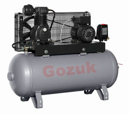 When installing a variable frequency drive is that the air ends (i.e. impellers) are usually custom made for the air compressor. ...
 When installing a variable frequency drive is that the air ends (i.e. impellers) are usually custom made for the air compressor. ...
Select a right Variable Frequency Drive
 Before selecting a Variable Frequency Drive (VFD) for an existing electric motor, it's important to know the purpose and ...
 Before selecting a Variable Frequency Drive (VFD) for an existing electric motor, it's important to know the purpose and ...
Variable Frequency Drives control AC motor for energy savings by adjustable speed, for short VFD, also named variable speed drives and frequency inverter.

